Interfacing STM32-Discovery with ST7066u LCD
- Kusala Bandara
- Nov 1, 2018
- 3 min read
Updated: Nov 14, 2018
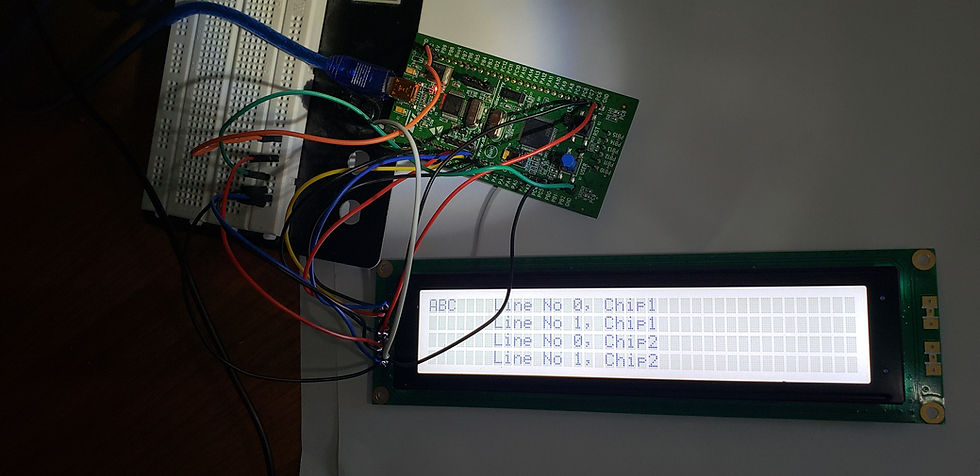
This LCD can be controlled by 4 bit bus or 8 bit bus. There are two chips in this LCD. Using each chip, you could display 80 characters.This project uses 4 bit bus for interfacing and could display 160 characters using both chips.I used IAR Systems.
Stm32-Discovery pins are wired to ST7066u as follows;
STM32-Discovery Pin Name: ST7066u Pin Name:
--------------------------- ------------------
PC0 DB4
PC1 DB5
PC2 DB6
PC3 DB7
PC13 E1(Chip1- Enable pin)
PC6 R/W
PC7 R/S
PC5 E2(Chip2-Enable pin)
GND V0(Con. adjustment pin-This must be connected to GND)
GND K(LED)
GND VSS
VCC A(LED)
VCC VDD
I encountered many problems and solved after spending hours. There are a number of things that you have to be careful about when wiring,
If you need only 2 lines to be used on LCD , only one of the enable pins (E1 or E2) has to be wired. If you need all four lines on LCD, you must wire both E1 and E2. I spent many hours trying to display on all four lines using only one chip. By wiring and enabling both chips, I could access all four lines.
V0 - Contrast Adjustment pin must be connected to GND. I tried my code without connecting V0 to GND. My code ran smoothly but display nothing on LCD. Connecting V0 to GND solved my problem.
The order of connecting pins DB4 -DB7 to PC0-P3 is important. Connecting DB4-DB7 to P3-P0 didn't give me any result since bits were shifted and gave meaningless commands,
My Code:
main.c
#include "stm32f10x.h"
#include "STM32vldiscovery.h"
#include "LCD.h"
int CHIP1=1;
int CHIP2=2;
GPIO_InitTypeDef GPIO_InitStructure;
TIM_TimeBaseInitTypeDef timerInitStructure;
void Timer_Configuration(void);
void Delay_ms(int ms);
int main(void)
{
RCC_APB2PeriphClockCmd( RCC_APB2Periph_GPIOC , ENABLE);
RCC_APB1PeriphClockCmd(RCC_APB1Periph_TIM2,ENABLE);
LCD_CtrlLinesConfig();
LCD_Init(CHIP1);
LCD_Init(CHIP2);
//setting the starting position of the cursor
//row=0, col=0,chip no=1
LCD_setCursorPosition(0,0,1);
//sending a character for chip1 to display
//char=A,data/command=Data ,chip no=1
LCD_sendByte('A',1,1);
LCD_sendByte('B',1,1);
LCD_sendByte('C',1,1);
LCD_setCursorPosition(0,7,1);
//sending a string for chip1 to display
//string="Line No 0, Chip1", chip no=1
LCD_printString("Line No 0, Chip1", 1);
LCD_setCursorPosition(1,7,1);
LCD_printString("Line No 1, Chip1", 1);
LCD_setCursorPosition(0,7,2);
LCD_printString("Line No 0, Chip2",2 );
LCD_setCursorPosition(1,7,2);
LCD_printString("Line No 1, Chip2", 2);
while (1)
{
}
}
void Timer_Configuration()
{
timerInitStructure.TIM_Prescaler = 23999;
timerInitStructure.TIM_CounterMode = TIM_CounterMode_Up;
timerInitStructure.TIM_Period =65535;
timerInitStructure.TIM_ClockDivision = TIM_CKD_DIV1;
timerInitStructure.TIM_RepetitionCounter = 0;
TIM_TimeBaseInit(TIM2, &timerInitStructure);
}
void Delay_ms(int ms)
{
TIM_SetCounter(TIM2,0);
TIM_Cmd(TIM2,ENABLE);
while(TIM_GetCounter(TIM2)<ms){
}
TIM_Cmd(TIM2,DISABLE);
}
LCD.h
void LCD_CtrlLinesConfig(void);
void LCD_Init(int);
void LCD_clearScreen(int);
void LCD_printString(uint8_t *,int);
void LCD_sendByte(uint8_t, int,int);
LCD.c
#include "stm32f10x.h"
#include "LCD.h"
void LCD_PulseEnablePin(int);
void delayMS(int);
void LCD_sendNibble(uint8_t,int);
void LCD_sendCommand(uint8_t,int);
//void LCD_sendByte(uint8_t, int,int);
int CMD = 0;
int DATA = 1;
void LCD_Init(int chip)
{
delayMS(40);
GPIOC->BSRR = GPIO_Pin_3|GPIO_Pin_2|GPIO_Pin_1|GPIO_Pin_0;
GPIOC->BSRR = GPIO_Pin_13;
GPIOC->BSRR = GPIO_Pin_6;
GPIOC->BSRR = GPIO_Pin_7;
GPIOC->BSRR = GPIO_Pin_5;
GPIOC->BRR = GPIO_Pin_3|GPIO_Pin_2|GPIO_Pin_1|GPIO_Pin_0;
GPIOC->BRR = GPIO_Pin_13;
GPIOC->BRR = GPIO_Pin_6;
GPIOC->BRR = GPIO_Pin_7;
GPIOC->BRR = GPIO_Pin_5;
if (chip == 1){
LCD_sendNibble(0x03,1);
delayMS(5);
LCD_sendNibble(0x03,1);
delayMS(5);
LCD_sendNibble(0x03,1);
delayMS(5);
//set 4bit interface
LCD_sendNibble(0x02,1);
//delayMS(2);
//sending function cmd and two line display
LCD_sendCommand(0x28,1);
delayMS(2);
//sending display cmd,display on and cursor on
LCD_sendCommand(0x0F,1);
delayMS(2);
//sending entry mode cmd and cursor increment
LCD_sendCommand(0x06,1);
//delayMS(1);
//delayMS(1000);
LCD_clearScreen(1);
}
if (chip == 2){
LCD_sendNibble(0x03,2);
delayMS(5);
LCD_sendNibble(0x03,2);
delayMS(5);
LCD_sendNibble(0x03,2);
delayMS(5);
//set 4bit interface
LCD_sendNibble(0x02,2);
//delayMS(2);
//sending function cmd and two line display
LCD_sendCommand(0x28,2);
delayMS(2);
//sending display cmd,display on and cursor on
LCD_sendCommand(0x0F,2);
delayMS(2);
//sending entry mode cmd and cursor increment
LCD_sendCommand(0x06,2);
//delayMS(1);
//delayMS(1000);
LCD_clearScreen(2);
}
}
void LCD_printString(uint8_t *Str,int chip){
uint8_t *c;
c=Str;
while((c!=0)&& (*c!=0)){
LCD_sendByte(*c,1,chip);
c++;
}
}
void LCD_setCursorPosition(uint8_t row, uint8_t col,int chip){
uint8_t address;
if (row==0){
address=0;
}else{
address=40;
}
address|=col;
LCD_sendCommand(0x80|address,chip);
}
void LCD_CtrlLinesConfig(void){
GPIO_InitTypeDef GPIO_InitStructure;
/* Enable GPIO clock */
RCC_APB2PeriphClockCmd(RCC_APB2Periph_GPIOC,ENABLE);
/* Configure NCS in Output Push-Pull mode -Enable Pin(E1)*/
GPIO_InitStructure.GPIO_Pin = GPIO_Pin_13;
GPIO_InitStructure.GPIO_Speed = GPIO_Speed_2MHz;
GPIO_InitStructure.GPIO_Mode = GPIO_Mode_Out_PP;
GPIO_Init(GPIOC, &GPIO_InitStructure);
/* Configure NCS in Output Push-Pull mode -Enable Pin(E2)*/
GPIO_InitStructure.GPIO_Pin = GPIO_Pin_5;
GPIO_InitStructure.GPIO_Speed = GPIO_Speed_2MHz;
GPIO_InitStructure.GPIO_Mode = GPIO_Mode_Out_PP;
GPIO_Init(GPIOC, &GPIO_InitStructure);
/* Configure NWR(RNW),in Output Push-Pull mode -R/W*///read or write
GPIO_InitStructure.GPIO_Pin = GPIO_Pin_6;
GPIO_InitStructure.GPIO_Speed = GPIO_Speed_2MHz;
GPIO_InitStructure.GPIO_Mode = GPIO_Mode_Out_PP;
GPIO_Init(GPIOC, &GPIO_InitStructure);
/* Configure RS in Output Push-Pull mode -Reset Pin*///Data /Instruction
GPIO_InitStructure.GPIO_Pin = GPIO_Pin_7 ;
GPIO_InitStructure.GPIO_Speed = GPIO_Speed_2MHz;
GPIO_InitStructure.GPIO_Mode = GPIO_Mode_Out_PP;
GPIO_Init(GPIOC, &GPIO_InitStructure);
//PC0 for LCD pin4(PD4)
GPIO_InitStructure.GPIO_Pin = GPIO_Pin_0;
GPIO_InitStructure.GPIO_Speed = GPIO_Speed_2MHz;
GPIO_InitStructure.GPIO_Mode = GPIO_Mode_Out_PP;
GPIO_Init(GPIOC, &GPIO_InitStructure);
//PC1 for LCD pin3(PD5)
GPIO_InitStructure.GPIO_Pin = GPIO_Pin_1;
GPIO_InitStructure.GPIO_Speed = GPIO_Speed_2MHz;
GPIO_InitStructure.GPIO_Mode = GPIO_Mode_Out_PP;
GPIO_Init(GPIOC, &GPIO_InitStructure);
//PC2 for LCD pin2(PD6)
GPIO_InitStructure.GPIO_Pin = GPIO_Pin_2;
GPIO_InitStructure.GPIO_Speed = GPIO_Speed_2MHz;
GPIO_InitStructure.GPIO_Mode = GPIO_Mode_Out_PP;
GPIO_Init(GPIOC, &GPIO_InitStructure);
//PC3 for LCD pin1(PD7)
GPIO_InitStructure.GPIO_Pin = GPIO_Pin_3;
GPIO_InitStructure.GPIO_Speed = GPIO_Speed_2MHz;
GPIO_InitStructure.GPIO_Mode = GPIO_Mode_Out_PP;
GPIO_Init(GPIOC, &GPIO_InitStructure);
}
void LCD_clearScreen(int chip){
LCD_sendCommand (0x01, chip);
LCD_sendCommand (0x02,chip);
}
void LCD_sendCommand (uint8_t cmdValue,int chip){
LCD_sendByte(cmdValue, CMD,chip);
}
void LCD_sendByte(uint8_t cmdValue,int CMD_DATA,int chip){
if ( CMD_DATA == 0){
GPIOC->BRR = GPIO_Pin_7;
}else{
GPIOC->BSRR = GPIO_Pin_7;
}
//sending high nibble
LCD_sendNibble(((cmdValue & 0xF0)>> 4),chip);
//sending low nibble
LCD_sendNibble((cmdValue & 0x0F),chip);
}
void LCD_sendNibble(uint8_t nibble,int chip){
GPIOC->ODR &=~(GPIO_Pin_3|GPIO_Pin_2|GPIO_Pin_1|GPIO_Pin_0);
GPIOC->ODR |=nibble;
LCD_PulseEnablePin(chip);
}
void LCD_PulseEnablePin(int chip){
if (chip==1){
GPIOC ->BRR = GPIO_Pin_13;
delayMS(200);
GPIOC ->BSRR = GPIO_Pin_13;
delayMS(200);
GPIOC ->BRR = GPIO_Pin_13;
delayMS(200);
}else {
GPIOC ->BRR = GPIO_Pin_5;
delayMS(200);
GPIOC ->BSRR = GPIO_Pin_5;
delayMS(200);
GPIOC ->BRR = GPIO_Pin_5;
delayMS(200);
}
}
void delayMS(int ms)
{
TIM_SetCounter(TIM2,0);
TIM_Cmd(TIM2,ENABLE);
while(TIM_GetCounter(TIM2)<ms){
}
TIM_Cmd(TIM2,DISABLE);
}


Comments